Robot Diagnostic

(current version on github)


(v4.002)
by Dan Peirce B.Sc.

Nov. 18, 2010

Overview
The purpose of the Robot Diagnostic program is primarily to test the correct functioning of the different parts of the robot. The students often add new code to their programs and find the robot stops working in ways they don't think are related to their new code. It is nessesary to have a program that can test all aspects of the robot to ensure it works. That is the puropse of the diagnostic program. It was designed to be easy to use by students, lab instructors and technicians.

The program was written to be used with hyperterminal

(although I have also written a Perl/TK script that includs a GUI and can be run on a PC that has Strawbarry Hill Perl installed [as well as the following perl modules Tk and Win32::SerialPort] ---- note that Tk must be compiled and installed and this takes some time -- more at  PerlTkGUIdiag.html  ).
The robot is connected to a PC with a simple passive cable. The program uses a menu system that is easy to navigate.

Oct. 26, 2010 (rev. Oct 27, 2010)

Significant changes to main.c were made for version 4.001 (4.002 fixed a bug). The state machine for the menu system has been retained but it is now the default state of a more encompassing state machine. The function pointer for the new robot diagnostic state machine is called diagnostic_state and as of this version of the program it can point at one of the four possible states. The function pointer concept is presented in some detail with regard to the menu system function pointer. The idea is the same here.
 

state transition diagram

The menu system runs within the process_command state. The menu system must be in the motor menu1 state in order for the jog option to be available. Restructuring the program in this way should permit the addition of other non menu driven states. For example the simple line follower program itself could be added as a new state of the diagnostic program.

Note that the ovals in the state transition diagram indicate program states. The arrows indicate possible state transitions. The letters adjacent to the arrows indicate a keyboard press in hyperterminal (or a graphical button activated by a mouse press if using the Perl/tk GUI). The arrow without a letter indicates an automatic state transition.

The jog1 and jog2 states both themselves contain a series of sequential sub-states.

Before the diagnostic state machine is started an initialzation function from sumovore.c is run. As part of the initialization of the robot hardware flags are read to determine what type of reset has occured. More on this at  Changes to sumovore.c and Sumovore.h .


Oct. 22, 2010

Files specific to version 4.002 can be found at this link


Sept. 2, 2010
Bluetooth restults moved to a new page  see bluetooth.html


August 24, 2010
Considering modifying a brainboard to use bluetooth.
<added Oct. 22, 2010> Note that while I have done this out of curiosity it is not needed to use the diagnositc program; however, it could be used to remove the tether between the robot and the PC and allow the PC to gather data as the robot moves around a course or maze.


July 30, 2010

Created a simple graphical interface that allows one to interact with the Robot Diagnostic program with mouse clicks rather than typing keyboard keys. More at the link ->   gui/PerlTkGUIdiag.html or in this iframe


July 6, 2010

Version 4.001 of the Robot Diagnostic program now allows one to stop the jog cycle using either a "u" or a "U" on the PC keyboard. It also allows one to switch from a jog1 sequence to a jog2 sequence by typing a "2" (one can switch back by typing a "1". At the moment the difference between jog1 an jog2 is only in the motor speed. jog2 is at full speed while jog1 is a medium speed.
 robot_diagnostic4001.hex

To accommodate different jog sequences (and the possibility of additional sequences) a simple state machine was added to main.c. The new state variable is called diagnostic_state. diagnostic_state is a pointer to a function. In this version diagnostic_state can be one of four values (shown in the table below).
 

diagnostic_state = jog1_state;
diagnostic_state = jog2_state;
diagnostic_state = process_command;
diagnostic_state = stop_state;
same as version 3.000 jog sequence
new jog sequence
process_command is the same function used in version 3
new state used for transition from jog1 and jog2 back to process_command

The file command_list.h has also been updated with new commands. The commands were added so that the function pointer variable diagnostic_state could have limited scope (only in the file main.c).

The files menu.c, sumovore.c and interrupts.c have also been updated.

all files in version 4.001


June24, 2010

An updated version of the diagnostic program will be coming soon for two reasons.
  1. The existing jog sequence created BrownOut Resets on version 1.0 robots before I started added an extra 22 microFarad capacitor to the output of that regulator. Now this capacitor is in place it appears a different jog sequence is more likely to cause trouble.
    • The output of the regulator was somewhat unstable when it lacked a large capacitor near the output pins. This problem showed up at medium speed. It seems plausible the reason was the PWM created a lot of edges and the transients associated with those edges feed the instability in the regulator.
    • With the instability fixed BORs are not happening with fresh batteries. As the batteries become depleted the chances of the Low Voltage Detect being activated becomes greater. The event most likely to cause this is having both motors reverse direction at the same time (this draws a lot of current). This could be tested for with a Jog sequence that runs the motors at full speed and allows the motors to obtain full speed before reversing. The new version of the program will probably have two or more jog sequences.

    •  
  2. The changes to sumovore.c and interupts.c should be incorparated into the simple curve follower project. In that project the need for further tweeks to sumovore.c are apparent and it would be best to have only one sumovore.c file so that will result in further small changes in the diagnostic project.
At the moment I have the sense that we can avoid the addition of a extra battery for the brainboard. Additional testing would be helpful to see how much difference it would make. I suspect that it would allow the use of more depleted batteries but the question remains of how useful that would be. Would it be worth the addition of the extra battery?


April 23, 2010 

On April 22 a new feature was added to the diagnostic program that is intended to find a value for the threshold that will ensure the line can not be lost between two sensors. (this works well on the Richmond robots with adjusted sensor resistors but not on the Surrey robot I tested).
Files for this project can be found at the following links:
 
main.c    menu.c menu.h  robot_diagnostic.hex
 process_command.c    process_command.h  motor_control.c motor_control.h
 sensor.c  sensor.h  sumovore.c  sumovore.h

osc.c and osc.h are also needed and are expected to be found in the folder "..\Functions".

(added April 27, 2010) The source files contain few comments. For an overview of how the program works click on this link or on the image of the State Diagram for the Menu system of the Diagnostic Program for the Robot (see below in April 26, 2010).


Communication with the robot is accomplished with hyperterminal. The configuration file for hyperterminal is here:
 

 robot_diagnostic.ht

A simple passive cable is needed to connect between the robot and the PC COM1 port. Page 13 of the PIC brainboard V 2.0 manual PIC brainboard V 2.0 manual shows the connections between the DB9 connector and pins that fit into the brainboard. As suggested I used a cable from a dead serial mouse for the connector and cable.

Note the level shifter is built into the new Brainboard version 2's so there is no need for the spark fun level shifter.
(image added Nov. 11, 2010)


April 26, 2010

The diagnostic program that runs on a robot works through a menu system. The robot must be connected to a computer with a simple passive cable.

The menu system has been inplemented as a state machine. Click on image below for a link that gives the details. (rev. May 14, 2010 -- there is more detail for both the Motor Menu 1 state and the Sensor Menu 1 state; these have been put into new images -- click on image below  ).

The top menu of the menu system looks like this screen shot below. There are essentially two choices at this level: motor or sensor.

In hyperterminal you must enter either m or S for motor or sensor.
In this HTML page you can click on the link to see the next menu...
   Kwantlen Polytechnic University
             APSC1299
   program by Dan Peirce B.Sc.
   version 1.100 April 22, 2010

        Top Level Menu

        m => motor
        S => sensor
        ? or h => help print this menu

_


May 3, 2010

The documentation has not kept up with the new versions of the diagnositic program.
 
rev. Nov. 18, 2010
Perhaps I should make clear that I have concluded that optical isolation is not needed in our case. I also don't expect an additional battery will be needed. Those ideas are discussed below but the result of that investigation was to add a capacitor to the mainboard of version 1.0 robots and to enable features already built into the microcontroller to improved reliability.

In my experience optical isolation is typically used when:

  1. interfacing to AC circuits.
  2. in industrial installations in which it might be possible for control wiring and power wiring to be accidentally shorted together in a mishap.
  3. when the wires are very long (meaning they go beyond the interior of a  single building).
I believe that the motor driver IC provides sufficient isolation in our case with small PM motors and very short wires. This is in regard to the quote of Mazidi, Mckinlay and Causey down below! These issues were investigated and I think we can now put them to rest.

It has been found that brown out conditions can be created. An extra battery was added so that the PIC had a separate 5v supply but the brownouts persisted (prior to June this had only be tried on version 1.0 robots -- added June 17, 2010). The next step is to add optical isolation between the PIC and the motor driver IC (the L293D). It appears this can be done without modifying the existing boards if new boards are added between the mainboard and Brainboard. (it does not now seem that is will be necessary!!! -- added June 17, 2010)

Note at  battery_replacement.html#optoisolation

I should point out that in PIC Microcontroller and Embedded Systems by Mazidi, McKinlay and Causey it is suggested that "the PIC18 is protected from EMI created by the motor brushes by using an optoisolator and a separate power supply." 
In Figure 17-18 page 656 they show an opto isolator used with the L293 (same driver chip used on the sumovore) and separate power supplies are suggested PIC and the L293 driver. I have run into hobbyists who recommend modifying the sumovore to use a separate battery for the PIC to avoid unexpected resets.
 
(rev. May 14, 2010) The plan that was outlined in the box shown below is starting to seem like too much work. Last night I thought of an alternate plan which would require fewer optical isolators (just 3 rather than 6) and would require no further changes to the existing robot or brain board 2! One would add circuits and a battery to an expansion board available from microchip.

In this scenario the PIC on the brain board would continue to control the robot as before; however, the student program would be run in a second PIC on an add-on board. The add-on board would have it's own power supply and would connect to the brain board through optical isolators so it would in fact be completely electrically isolated from the robot!

The PIC on the brain board v2 would have just one reliability feature enabled; the watchdog timer would be enabled. This would mean that if the program running on this PIC stopped executing the code in the normal way the watchdog timer would time out causing the PIC to reset and so reenter a known state. This would occur in the order of 30 to 40 ms. 

I have found that if I enable the brownout reset the resets occur to frequently with the existing setup. The brownout circuit must be sensitive to conditions that actually only rarely cause the PIC fail. This can be tolerated except when it is important not to lose any values stored in RAM. On reset all values in RAM are lost. This is not important with regard to the low level control close to the hardware as long as the condition does not persist for too long. It is only on the order of 30 ms I think this would hardly be noticeable as long as it does not happen too frequently.

At a higher level one must maintain flags and other variables regarding if the robot has recently seen a line off to the right or the left. In the case of a maze one would keep an internal map of the maze. No resets can be tolerated. If the higher functionality was maintained in a PIC completely isolated from the electric EMI of the motors is should be robust and reliable.
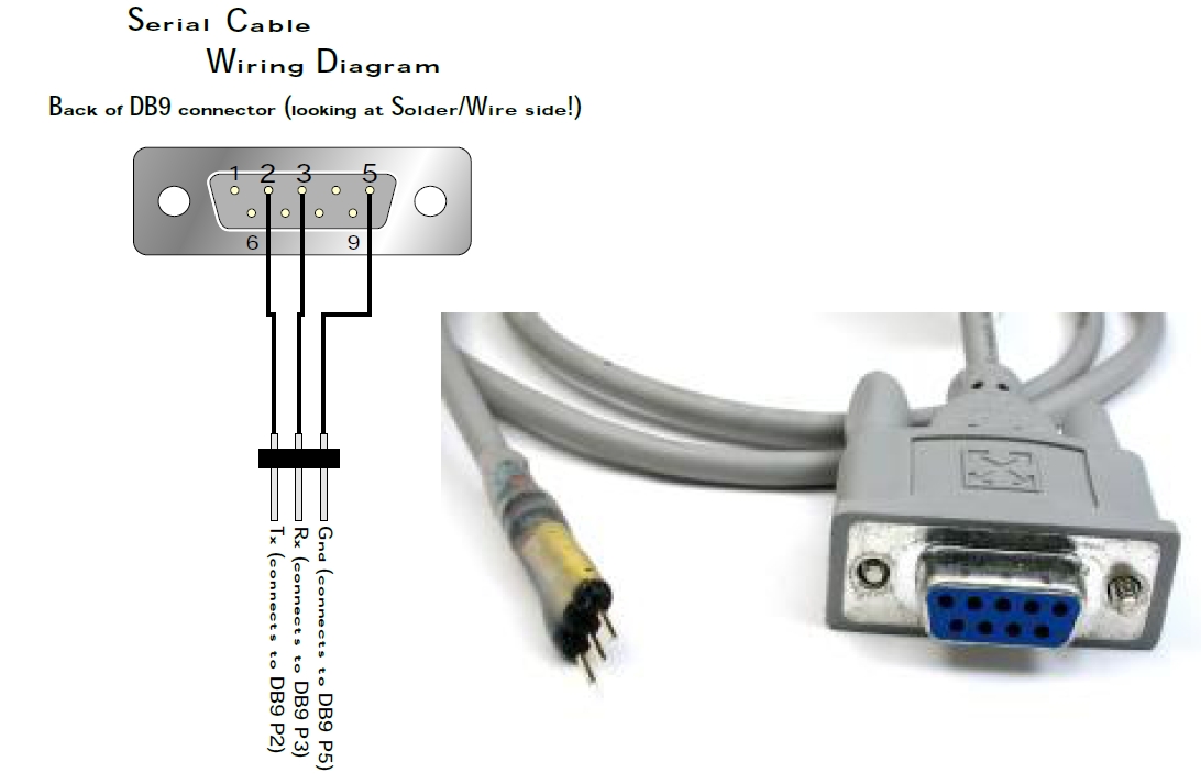


(rev. May 18, 2010)
Having looked at using the I2C interface or the RS232 interface I have decided it would be simpler to use the RS232 interface although this will require the addition of one jumper to the version 2 brain board. 

Using the I2C interface would not have required any change to the version 2 brain board; however, it would be much more complex to build an isolation circuit given the bi-directional nature of the I2C interface lines.

From a softward point of view the RS232 seems more straight forward. The purpose of I2C is to allow a microcontroller to talk to several peripherals over the same two line interface. That adds complexity that is not required here. For example the I2C message includes an address so the specified peripheral will respond. The microcontroller is the master and the peripherals are slaves (they only send information reqested).

The intent of RS232 is more our actual situation. We will have two microcontrollers talking to each other peer to peer. RS232 will allow messages to be going in both directions at the same time. This will allow the software to be simpler. The complication is the built in level shifting interface intended to let the brain board talk to a PC. That can be worked around. For example the expansion board can be removed when the diagnostic program is being run on the robot.

(rev. June 16, 2010) On the 15th tests showed very different results for version 1.0 robots and version 1.1 robots (currently there are only 2 version 1.1 robots in Richmond.

from email from me to Mike C.


I have setup the diagnostic program to test for brownouts and got some surprising results when comparing old version 1 robots to the newer version 1.1 robots. 

I only have two of the newer robots at the Richmond campus but in testing today so far I have found my jog sequence always causes a brown out reset on version 1 robots and never does on version 1.1 robots (with fresh batteries).  I did the test with fresh out of the box batteries and batteries that had a total of 8.7 volts (voltage measured when the robot was on and the motors were disabled).

Note that I tried moving a brainboard from an the new 1.1 robot to the old 1.0 robot and the result was the same; there was a reset on the 1.0 version robot.

The first implication of this is that the version 1.1 robots may be a great deal more reliable than the version 1.0 robots. The new version of the robot main board has what looks like a more logical layout with shorter ground traces. see http://www.kwantlen.ca/science/physics/faculty/dpeirce/notes/sumovore_maintenance_log/sumovoreVersions.html
and
 More on this below at  Low votage detect

I guess the question then would be is the isolation still necessary with version 1.1 of the robot (it may be a lot easier to simply use version 1.1 robots if that is all it takes to get better reliability).

I should try more tests with older batteries.

indication of brownout reset <BOR> (running version 1.0 robot)
Note it should say version 3.000 (guess I forgot to change the message in the program).

Where as the version 1.1 robot just kept going and going (I stoped it after 1000 jogs -- <POR> indicates a power on reset i.e. I turned the power off and back on) 


Low Voltage Detect

When I ran tried the jog sequence on a new version 1.1 robot with old batteries I found I started to get low voltage detection when the total voltage on the batteries was drained to about 6.1 volts. Initially the voltage was higher but after 3069 jog cycles the batteries had discharged down to 6.1 volts and the LVD's started to occur. Initially they were occurring every 200 or so jog cycles. As the batteries continued to discharge the frequency of LVD's increased.

There is a significant difference between the LVD and the BOR. The voltage difference between the two is small. The LVD causes an interrupt. The interrupt service routine turns off most of the IO of the PIC as quickly as possible in an attempt to slow down the voltage drop. If a BOR occurs it means there was insufficient time to avoid having the voltage drop to the BOR level. If a LVD is indicated then the interrupt service routine was able to avoid a BOR by turning off the motors (and LED's). This means the BOR is an indication of a large dV/dt and a LVD is an indication of a smaller dV/dt.


[correction made on Feb. 25th. 2011 -- including the strike out of characters above]

If a low voltage condition last longer than TBOR then a BOR condition exists. The datasheet gives only a minumum value for TBOR .
TBOR > 200 micro seconds

It appears that changing the layout for the version 1.1 robot reduced the dV/dt  [correction --- repaced dv/dt with duration] duration that the PIC sees a low voltage condition on the 5 volt supply. I'm guessing that on the ground lines the high current path to the motor controller and the low current path to the PIC was separated so that noise on the ground of the high current path would have less effect on the PIC and the brainboard in general. Also, it is possible the the location of the large filter capacitor is more effective on the version 1.1 board. 

I have had a close look at the layout of the version 1.0 and version 1.1 boards and it appears that the version 1.1 board has a smaller dv/dt because the 1000 micro farad capacitor C1 is connected very close to the output of the regulator. On the version 1.0 board the capactor C1 is a long way from the regulator and the motor driver is between (a bad layout). See http://www.kwantlen.ca/science/physics/faculty/dpeirce/notes/apsc1299/2010/mainboard/ground_layout.html

In the image below black indicates a highlighted ground trace on the component side of the board. Gray is a highlighted trace ground trace that is on the solder side of the board (dark gray is a trace I could see -- light gray is a trace I am guessing must be there -- I'm guessing because I don't currently have access to one of these boards that does not have a bracket obscuring where I think the trace most likely is and the manual is no help because it does not show the solder side of the new board; the solder side photo is clearly the old 1.0 version board). 


Bob brought over a robot from Richmond today. I used the diagnostic program to look at readings from the sensors. I found the sensors on that robot were saturated as I would expect. The automatic threshold selection option of the diagnostic program will not work with the highly saturated sensors. I tried setting the threshold manually and found with a setting of 35 the line could not be lost between any two sensors but with a setting of 40 it could be. The setting for the calibrated richmond sensors typically is between 450 and 512 and the automatic setting procedure works.
(prior to May 14) Solarbotics calls the controller board a brainboard and I have been doing the same. I am considering starting to call it the PIC board or microcontroller board.  The new boards could be called isolation boards 1 and 2. It seems two boards will be needed because the connectors to the mainboard need to be in the same relative position as the connectors to the PIC board.

The plan is (was prior to May 14 -- it was noted on May 14 that this would be too much work hardware wise -- see alternet plan May 14 and 18 above -- note as of June 15 this has not yet been implemented) to make the isolation between the main board and the PIC board as compleate as reasonably possible. Motor control outputs will go to optical isolators.

  • The five volt supply for the LED's will come from the PIC board independed supply.
  • The supply for the sensor side of the IR refective sensors will also come from the PIC board supply.
  • The IR emitters will be supplied from the main board supply.
  • The one point where isolation will not be complete is the IR emitters and IR sensors share a common ground. This would not necessary but the sensor board is designed such that there is a copper trace directly between the IR emitter and IR sensor under each IR reflective sensor.  The only way to separate these would be to make a new replacement boards. I think we should be able to tolerate the point of contact between the two supply systems without getting Brownout conditions since it will be the only point of contact. I am considering running a ground wire from the sensor board to the PIC board to provide the return path for the sensors.

    I should test the new version of the main board to see if the brownout reset is an issue with it as well. I have been testing on Robot 07 (version 1 robot) because that was the one I was testing on back in 2008.


    May 4, 2010

    Version 3 of diagnostic program.
    1. At the time I posted this there are two version of jogx.c and motor_controlx.c. I am still deciding which I want to include and at any given time only one of the two varients of both files should be included in the project workspace.
    2. the bit rate for the USART is set in sumovore.c. The rate for this version of the program is 115200 bps. (for version 2 only it had been changed to 9600 bps).
    main.c menu.c menu.h command_list.h
    interrupts.c interrups.h process_command.c process_command.h
    jog1.c jog2.c jog.h robot_diagnostic.ht
    motor_control1.c motor_control2.c motor_control.h robot_diagnostic3000.hex
    sensor.c sensor.h sumovore.c sumovore.h