Notes by Dan Peirce B.Sc.
The ATmega32U4 MCU has limitations so I am considering methods to use a Microstick II with a PIC32MX150F128B piggybacked on the Zumo. This perhaps will be simplified through the use of the I2C interface bus on the Zumo. Some of the sensors on the Zumo are accessed via I2C. As designed the ATmega32U4 would be the master of the bus. For use with the Microstick II the ATmega32U4 would be reprogrammed as an I2C slave and the added PIC32MX150F128B would become the new master. The ATmega32U4 could continue to be used to read the line sensors. The condition of the line sensors could be read from ATmega32U4 via I2C and sensors like the accelerometer could be read directly using the I2C.
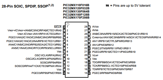
Although the PIC32MX150F128B runs at 3.3 volts some pins are 5 volt tolerant. Pins 17 and 18 used for I2C are 5 volt tolerant.
One big advantage of I2C is it requires just two wires on an open drain bus. Custom wiring would be minimal.
One could also continue to use the existing ATmega32U4 to run the motors. The PIC could send commands to the ATmega via the I2C bus that would set the duty cycle and direction of the motors. The high level student program would go into the PIC and the lowest level code would be preprogrammed into the ATmega (saving us some development time).
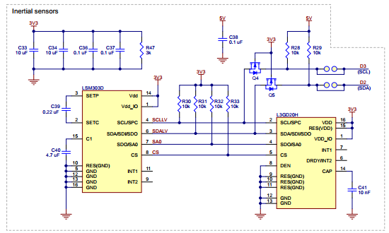
I have not yet tested this but I believe we can connect to the I2C bus via an expansion header on the Zumo. Note the SCL and SDA lines:
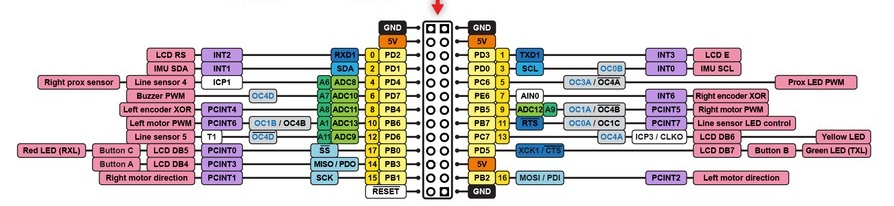
See https://www.pololu.com/docs/0J63/all#3.9
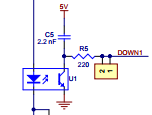
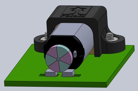
The Zumo has five reflective line sensors like the Solarbotics Sumovore. The method of reading the sensors is different on the Zumo. Rather than using a pull up resistor the Zumo uses a capacitor. The photo transistor pulls a current proportional to the reflected IR. The higher the current the faster the capacitor charges. The ATmega32U4 measures the time it takes for the capacitor to charge. Note the line voltage approaches ground as the capacitor charges because the other side of the capacitor is at Vdd.
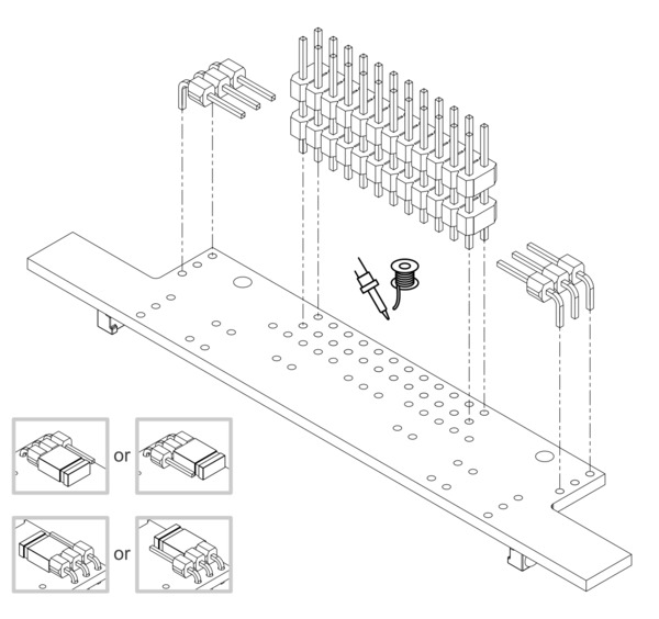
The assembled Zumo ships with five line sensors and three proximity sensors. Only three of the line sensors ship connected to the ATmega32U4 MCU. That configuration works for sumo events and other purposes. For line following one would want to change the configuration to use all five reflective line sensors. The change would involve moving jumpers that are soldered in place.
The signals from the sensors can be remapped by soldering in a wire from
the signal output to the desired I/O pin. You would also want to disconnect
the sensor output from the standard I/O pin so that pin can be used for
other purposes. For line sensor 1, line sensor 3, line sensor 5, and the
front proximity sensor, disconnecting the sensor involves cutting a trace
between the signal output and the standard I/O pin, which is labeled on
the board. For the line sensor 2, line sensor 4, the left proximity sensor,
and the right proximity sensor, you can simply move or remove the
corresponding jumper.
Quoted from https://www.pololu.com/docs/0J63/3.5
The jumpers that need to be moved are not visible on an assembled Zumo. The front sensor array board is easily removed by gently pulling the board away from the main board. Once removed the jumpers become visible. See https://www.pololu.com/docs/0J63/4 and page down to the Heading Front sensor array or click here https://a.pololu-files.com/picture/0J6707.600.jpg
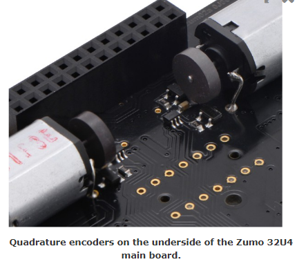