Buzzer Timer

for Kwantlen Science Challenge

by Dan Peirce B.Sc.


Nov. 22, 2007
The buzzer timer is built into a used computer speaker case. Pre-existing circuits from the speaker amplifier were retained. The timer operates as follows:
 
  1. The 9 Vdc 800 mA AC wall adapter plugs into the 9 Vdc power jack at the back of the speaker unit. The other jacks on the back of the unit are no longer used.
  2. The power switch, power LED and volume control operate as before. Four momentary switches have been added to the top of the case. They are labeled as: Buzz Now, Reset, ten sec. and five sec. The buzzer has 4 modes corresponding to the four switches. Pressing a switch will cancel the previous mode and activate the new mode unless the buzzer timer is already in that mode. If a switch is pressed that corresponds to the current mode nothing will change.
  3. The two time modes are time limited. Once timed out the current mode is automatically canceled and the buzzer timer will switch to the Buzz mode. The buzzer timer stays in the Buzz mode until it is canceled by pressing any of the other three switches.
  4. The time period of the timer is activated by the press of the switch and the time of the release is irrelevant as long as the button is released before the timer times out. The following is not expected to happen, but if the time switch is still pressed at the end of the timed period the timer will switch to the buzz mode momentarily then jump back to the timer mode starting a new time cycle. The modes would change too quickly in this case for the buzzer sound to be audible (in the order of 10s of microseconds).


More comments have been added to the file buzzer_timer.c
see buzzer_timer.zip
unused files (com.c and com.h) have been removed from the zip file.

The Pin assignments on the PIC18F4525 were made as follows:
 
input to amplifier circuit SPEAKER  PIN20
push button switch  TEN_SEC PIN21
push button switch  FIVE_SEC PIN22
push button switch  RESET PIN27
push button switch  BUZZ_NOW PIN28
Switch hole label

Schematic of circuits added to computer speaker to create the Buzzer Timer

Nov. 20, 2007
The buzzer itself was completed today. I don't have a lot of time to update this page at the moment. When I get a chance I will add more information about the circuit and operation instructions.

It looks like this. The AC-DC adapter is rated at 9 Vdc 800 mA.

Note that there is an on off switch on the front and a volume control. It seems that the Buzz Now button needs to be pressed harder than the others.

The switches and label look like this close up (the flash washed it out a bit).

The code for the PIC inside is contained in this zip file


Nov. 9, 2007
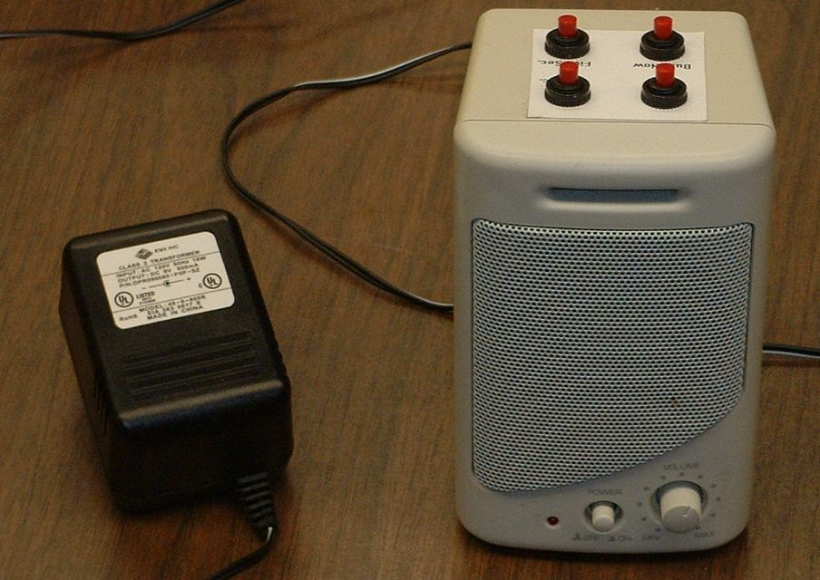
A computer speaker will be hacked into a 5 second -- 10 second timer buzzer for one of the science challenge events for 2007.

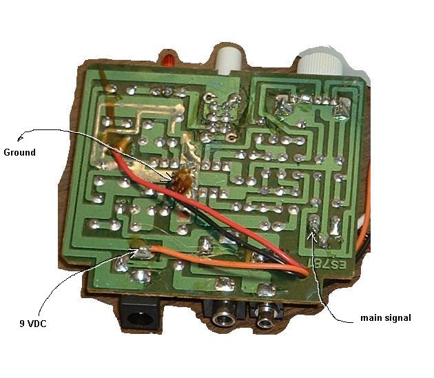
This image shows the circuit board from the computer speaker. Connection points are shown.

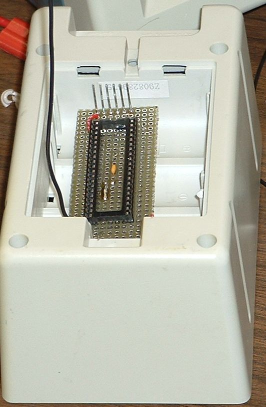
A custom PIC18F4525 microcontroller board is being prepared to fit into the battery compartment of the computer speaker. The PIC18F4525 microcontroller will be programmed in C language to respond to button switch inputs and it will also create the signal that will be amplified and fed to the speaker. The Pins along the top of the board will be used to program the microcontroller in circuit.

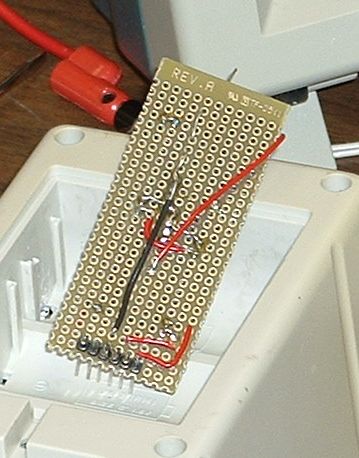
The image below shows the solder side of the PIC18F4525 custom board.

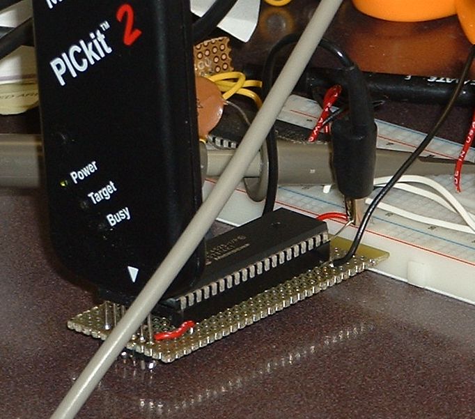
Downloading first test program

Waveform for Buzzer

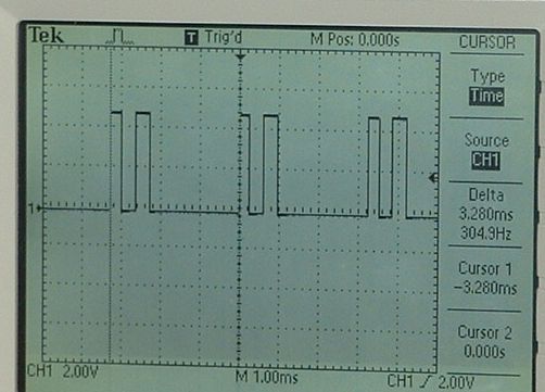
from the following program
 buzzer_timer.zip

Next I will work on the logic for the switches.