The display was purchased from the Canadian version of the RobotShop website:
Unfortunately they don't provide up to date information for the OLED module. The datasheet is for a previous version. The Libraries supplied for the display are written by Adafruit.
Initial testing was done with an Ardunino Uno as this was what was shown in the datasheet. Note the silkscreen on the v1.2 board does not match the v1.1 datasheet with regard to the pinout. I followed the silkscreen.
No external pull ups were added!
Downloaded and installed Arduino IDE for windows 7. (used installer for XP and up)
Downloaded libraries from elecfreaks site.
The libraries are actually from Adafruit. One can learn more about them here:
Two folders containing files were copied to c:\arduino\libraries
  C:\Users\Student\Downloads\EF03155-Paintcode\Code\Arduino_UNO_DEOM\Hardware I2C\Adafruit_GFX
  C:\Users\Student\Downloads\EF03155-Paintcode\Code\Arduino_UNO_DEOM\Hardware I2C\Adafruit_SSD1306
A new example became available in the IDE
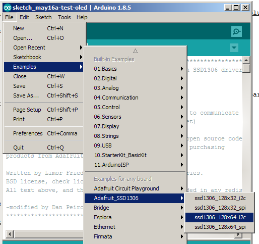
The example was copied and pasted into a new sketch.
Initially the sketch would not compile. The compiler error indicated that a variable needed to be a constant to be placed in program memory. The following line was changed (line appears just after macro definitions near beginning of file).
Once the const reserved word was added the sketch compiled.
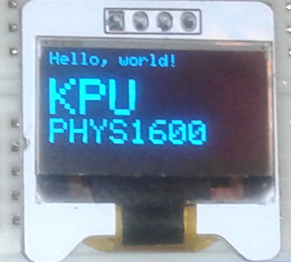
The display still remained blank. An I2C scanner Arduino sketch was used to find that the board responded to the address 0x3C. A line in the example was changed to include this address. Once this was done the display showed the example code.
Other modifications were made as I was interested in concentrating on the display of text rather than graphics.
This was recorded at the end of the day in a rush. I expect to get a better quality video soon -- it looks better in person. Also I will do some testing of different text sizes.
Code moved to new file to avoid clutter on this page.
It became apparent that the elecfreaks.com site provided an old version of the libraries and it seemed expedient to test the current version of the files.
It worked with a minor adjustment for the electfreak display.
As before the address of the display had to be adjusted.
Had to make a change to Adafruit_SSD1306.had
At line 73 changed which line was commented out.
   #define SSD1306_128_64
//   #define SSD1306_128_32
// #define SSD1306_96_16I forked the project on Github and made a new branch called 3rdparty.
Added a new branch to fork of Adafruit_SSD1306 repository Called exploring_text.
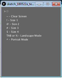
Added a new branch to fork of Adafruit_SSD1306 called terminal. The intent is to be able to send serial strings to the Arduino that will act as a controller for the display. The stream of characters could come from any MCU which would not need the graphics library ported. Current testing is being done with Arduino serial monitor but will follow up with project MCU.
display.setRotation(1); // results in a portrait orientation for text on the screen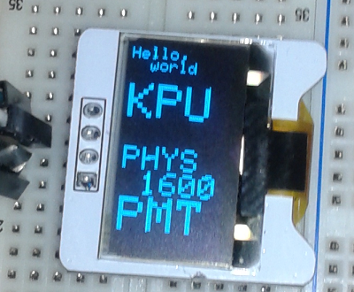
Added a new branch with SO (shift out) support. To facilitate multiple SO commands the sketch/program was converted to a state machine structure. This permits the ability to add parameters to a command. The set text position command for example requires X and Y coordinates as parameters for setting the cursor position.
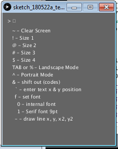
As of the time of this entry (June 6, 2018) The font has been changed to the 9 point Serif font. This font is easier to read than the built in font.
To save RAM space the F() macro is being used with string literals. This conserves RAM. (June 17, 2018)
A new branch was added which differs from terminal_so primarily in the look of the start screen.
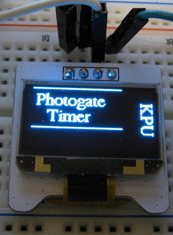
The code in the setup() function was simplified by breaking out lines responsible for the start screen into a separate function. A SO command was added so that this function can be called again after the screen is cleared. This refactoring will be merged back into the timer_so branch.
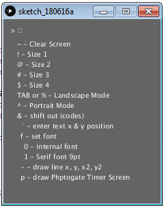
The tictactoe branch was merged into the timer branch to take advantage of new features. The essential difference now is in the default screen.
Tic tac toe branch allows easy setup of Tic Tac Toe screens for play.
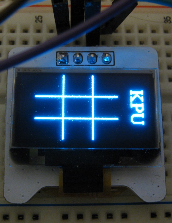
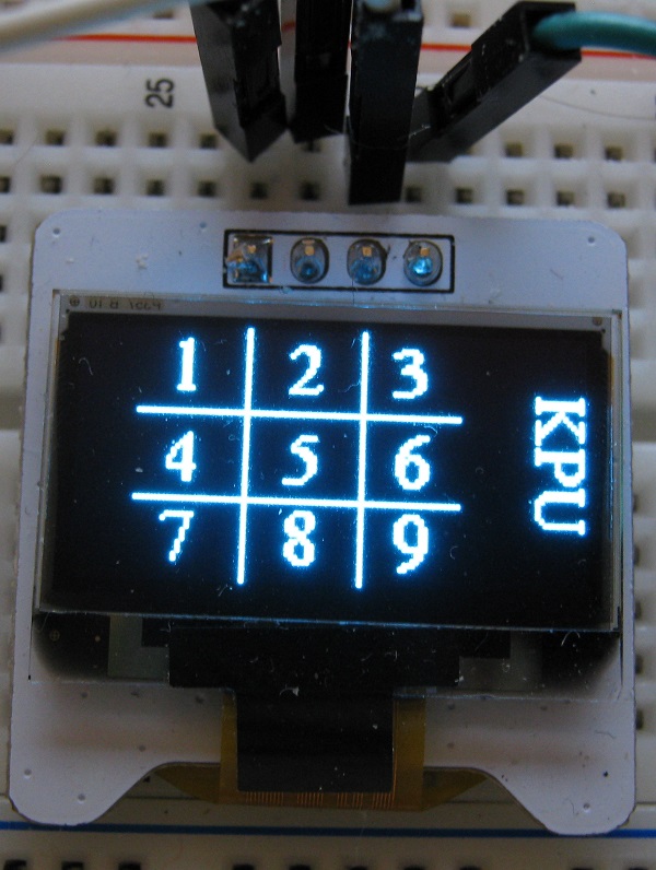
The next image shows the numbered positions corresponding to the nine positions that an X or and O can be placed. The numbers are added with the sequence: "&ts"
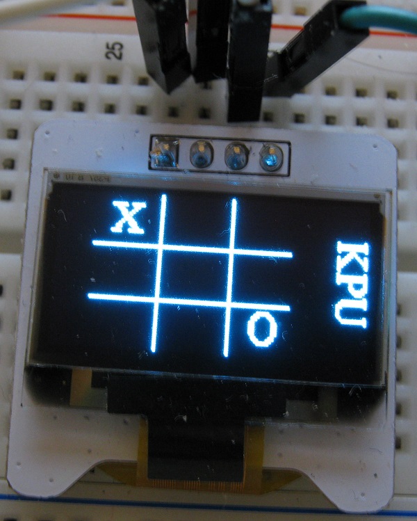
The next image shows an example.
The sequence shown above was typed into the Processing sketch. Note that the "&" is not sent as is to the "terminal" but is used in the sketch as it is easy to type. If one were writing a PIC program a 0x0E would be sent for the Shift Out command.
Menu items for Tic Tac Toe have been added for testing.
In the default state most ASCII characters sent will be printed if printable but do not appear on display until a newline/linefeed "" is sent (0x0A).
On May 28, 2018 moved testing from Arduino Uno to Adafruit Pro Trinket 5 volts. This board is much like the Uno when combined with a USB to serial adaptor board. The Arduino IDE sees the combination as the same as a Arduino Uno. The Pro Trinket will shrink the size of the project and reduce cost. The final project will not need the USB to serial adaptor board attached which will further reduce cost when we make a class set. I will continue to use the USB to serial board for programming and testing only.
The descriptions at https://github.com/danpeirce/photogate-box-ssd1306term have been updated frequently. That is currently the best place to read the details of this application of the terminal display.
The most recent version of the project is in the master branch. Many stages of the development of the project are preserved in the various branches.
The old Git PIC MCU photogate box repository was imported into a new repository and will be modified to make use of the graphics display terminal.
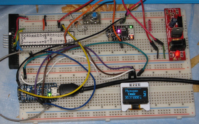
A simple exploratory project that combines a PIC MCU with the OLED terminal. This is essentially my first experiment in using the Pro 5+ Volt Trinket -- OLED graphics display combo as a display terminal for a PIC project.
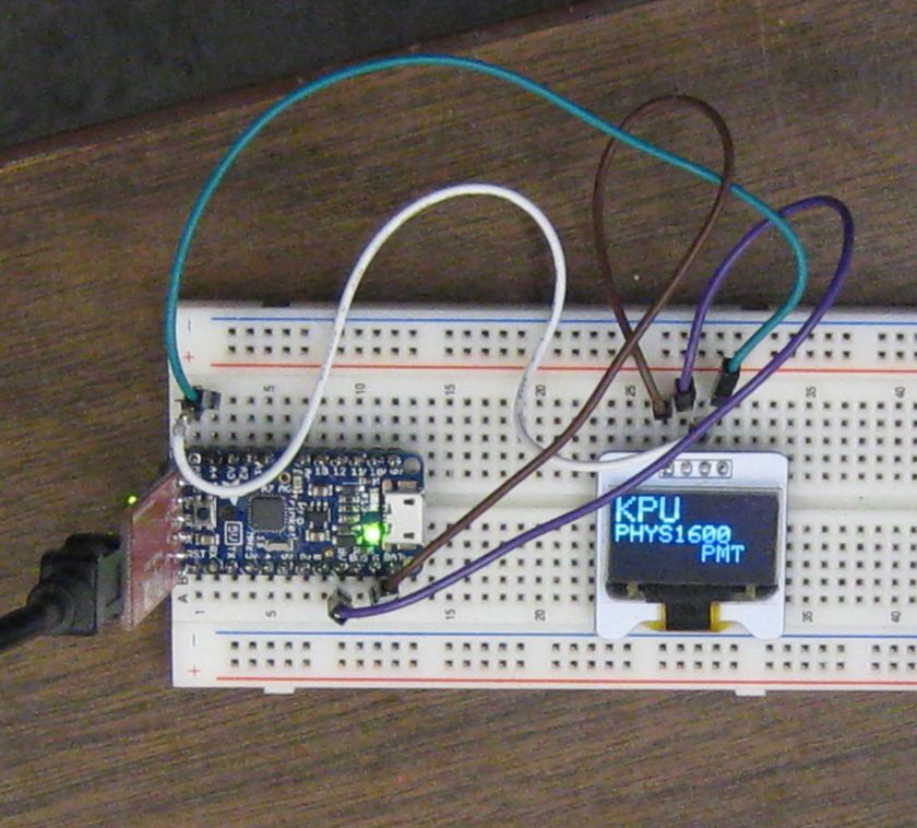
The Circuit with the PIC18F4525 and Display Terminal 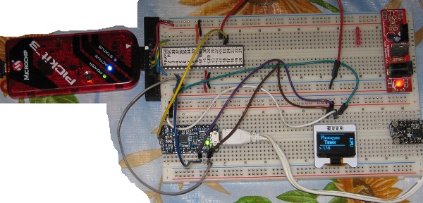
There are several possible methods of powering the Pro Trinket board which distributes power to the rest of the project.
The Pro 5+Volt Trinket board was powered from a USB to serial adapter board that was also used to program the Trinket.
The adapter is removed and power comes through a Micro B USB connector in the Trinket. VDD and ground is being distributed to the PIC MCU and the OLED display from the Trinket.
There is a jumper from the PIC Tx pin to the Trinket board Rx.
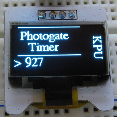
In an effort to eliminate flicker that was evident in the count line on the display a window state was created. There is no call to display.display() until a newline is received.
The main while loop running in the PIC for justcount is very simple. The count is free running and the time per cycle is not a prime consideration.
    while(1)
    {
        count++;
        if (count > 500000)
        {
            static unsigned int cycle = 0;
            static const char code[] = {SHIFTOUT, 'w', '2', 0};
            count = 0;
            printf("%s> %d\n", code, cycle);
            cycle++;
        }
}This branch explores posting a message to the display that indicates if a pushbutton switch has been pressed or released.
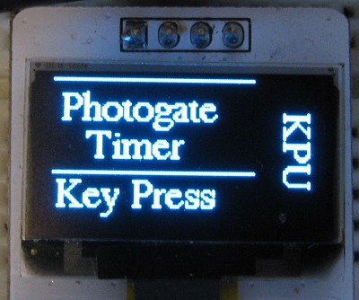
Since printf() does not return until all but the last two characters are sent it generally causes delays. Those delays could result in missed key presses. To avoid that issue sprintf() is being used rather than printf().
keyp = PORTDbits.RD2;
if (keyp != keyplast)
{
if (keyp == 1)
{
inIndexBuff = inIndexBuff + sprintf( buffer+inIndexBuff, "%sKey Press\n", code);
}
else
{
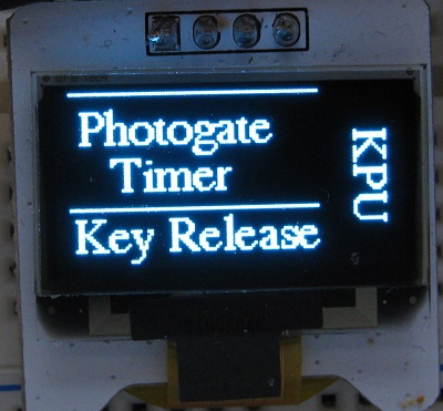
inIndexBuff = inIndexBuff + sprintf( buffer+inIndexBuff,"%sKey Release\n", code);
}
}
keyplast = keyp;There is also a task to send a byte to the USART whenever it is ready for one if the buffer is not empty..
        if(TXIF && (inIndexBuff > 0))
        {
            TXREG = buffer[outIndexBuff];
            outIndexBuff++;
            if (inIndexBuff == outIndexBuff)
            {
                inIndexBuff = 0;
                outIndexBuff= 0;
            }
        }
After speeding up the loop significant switch bounce became apparent. This was mitigated by reducing the frequency of checking the switch condition.
    while(1)
    {
        static int loopcount=0;
        if (loopcount > 500)
        {
            keypresstask();
            loopcount=0;
        }
        loopcount++;
        txbuffertask();
} It seemed more practical to have a copy of the terminal sketch in the PhotogateLC.c repository.
This branch counts the number of times a button switch has been pressed. This could be useful to ensure switch bounce has been deal with adequately.
place image
This branch was initially intended to time the interval between key presses. It became apparent testing would be more consistent if a photogate were simulated with a digital signal from another MCU. A Trinket M0 was available and used for this purpose.
The code for this branch is on Github.
The Trinket M0 code used to generate a period of about 20 seconds.
// the setup function runs once when you press reset or power the board
void setup() {
  // initialize digital pin 13 as an output.
  pinMode(13, OUTPUT);
  pinMode(0, OUTPUT);
}

// the loop function runs over and over again forever
void loop() {
  digitalWrite(13, HIGH);   // turn the LED on (HIGH is the voltage level)
  digitalWrite(0, HIGH);
  delay(10000);              // wait for 10 seconds
  digitalWrite(13, LOW);    // turn the LED off by making the voltage LOW
  digitalWrite(0, LOW);
  delay(10000);              // wait for 10 seconds
}
Notes on the Trinket M0 at link:
It was decided to rename the main file of the project and move unused functions to a different file. This change has now been cherry picked and merged into older branches.
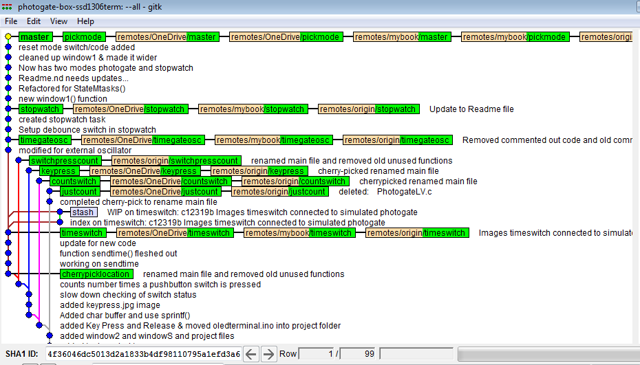
The hash that was cherry picked from is given below:
This branch was derived from timeswitch. The code was altered to work with an external 32 MHz rather than the internal oscillator used initially.
Watch for updates to this page.
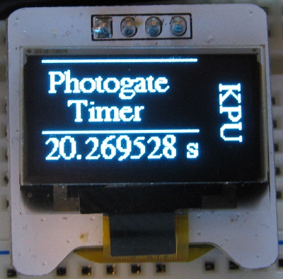
This branch was derived from timegateosc. The code was altered to time between start and stop button presses. This branch ignores the simulated photogate on the CCP1 input. The follow up branch will create a mode select to allow one to choose either mode of operation.
The function main() looks like this now:
void main(void)
{
    char gate_mode = 0;
    Delay10KTCYx(20);

    initialization();
    debounceSW.a_byte = 0;
    inputSW.a_byte = 0;

    while(1)
    {
        static unsigned int listTmr[] = {0,0,0,0,0,0};
        static unsigned int indexTmr = 0;
        static unsigned int cyclecount = 0;

        if(TXIF && (inIndexBuff > 0)) txbuffertask();
        if (PIR1bits.TMR1IF) // Timer1 clock has overflowed
        {
            PIR1bits.TMR1IF = 0; // reset Timer1 clock interrupt flag
            timerCountOvrF++;
        }
        inputSW.bit0 = PORTDbits.RD2;
        if (!debounceSW.bit0)
        {
            if (!inputSW.bit0 && (cyclecount>2)) cyclecount--;
            if (inputSW.bit0)
            {
                cyclecount++;
                if (cyclecount == 1)
                {
                    listTmr[indexTmr] = ReadTimer1();
                    indexTmr++;
                    listTmr[indexTmr] = timerCountOvrF;
                    indexTmr++;
                    running();
                }
            }
            if (cyclecount > 100)
            {
                cyclecount = 0;
                debounceSW.bit0 = 1;
            }
        }
        else
        {
            if (inputSW.bit0 && (cyclecount>2)) cyclecount--;
            if (!inputSW.bit0) cyclecount++;
            if (cyclecount > 100)
            {
                cyclecount = 0;
                debounceSW.bit0 =0;
            }
        }
        /* if (PIR1bits.CCP1IF)
        {
            listTmr[indexTmr] = ReadCapture1();
            indexTmr++;
            listTmr[indexTmr] = timerCountOvrF;
            indexTmr++;
            PIR1bits.CCP1IF = 0; //clear flag for next event
        } */
        if (indexTmr == 4)
        {
            sendTime(listTmr);
            indexTmr = 0;
            timerCountOvrF = 0;
        }
    }
}